
Technical Specifications
| Specification | Value |
|---|---|
| Architecture | 32-bit ARM Cortex M3 |
| Operating Voltage | 2.7V to 3.6V |
| CPU Frequency | 72 MHz |
| Number of GPIO pins | 37 |
| Number of PWM pins | 12 |
| Analog input Pins | 10 (12-bit) |
| USART Peripherals | 3 |
| I2C Peripherals | 2 |
| SPI Peripherals | 2 |
| Can 2.0 Peripheral | 1 |
| Timers | 3(16-bit), 1 (PWM) |
| Flash Memory | 64KB |
| RAM | 20KB |
Get Started
Linux driver installation: http://padcom13.blogspot.com/2015/12/getting-started-with-stm32-on-ubuntu.html
Windows
- Set up STM32CubeMX: https://www.st.com/en/microcontrollers-microprocessors/stm32f103c8.html
- Set up TrueSTUDIO: https://atollic.com/truestudio/
- Download and install other drivers through intermediate prompts
- End to end video tutorial to set up the development environment and getting started with a Blinky project:
- Tutorial video to help connect the ST-Link programming unit to the STM32 MCU:

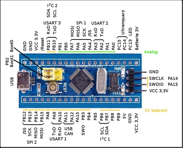
Pinout diagram of the ST-LINK programming unit - Debug to upload the code (.hex file) to STM32 and Resume to actually execute the code on the MCU.
💡
Note that in the programming unit, we connect to the pins 2, 4, 6, 8. The pins are respectively SWCLK, SWDIO, GND, 3.3V. Corresponding are connected in the STM32.
Debugging
Connecting STM32 to PC using Serial Adapter (or Arduino)
Use an Arduino and connect the RESET and GND pins together
Custom Bootloader (Windows App)
Setup [using Arduino] (DID NOT WORK OUT!!)


Points to note while connecting
- Connect the
RESETandGNDboth on Arduino to make it act like a serial adapter. - Connect the
GNDof STM32 andGNDof Arduino. - Connect the
3.3V pinof STM32 to3.3V pinof Arduino. - Connect the
PA9 (Tx)of STM32 to theRxof Arduino. - Connect the
PA10 (Rx)of STM32 to theTxof Arduino.
❌
This method did NOT work out!! Neither did removing the Atmel IC of the Arduino help.
Setup [using Serial Adapter / USB2TTL]

Setup [using ST-LINK Programming Unit]

Things to Remember
- While programming and testing the STM32 using the serial adapter, it is important to set the boot pins correctly, otherwise results are not correct. Pinout diagram here.
- Programming mode: Boot Pin 0 set to HIGH, Boot Pin 1 set to LOW
- Operation mode: Boot Pin 0 set to LOW, Boot Pin 1 set to LOW

- We use FLASHER-STM32 for flashing .bin files to the STM32. Available for Windows.
- We use stm32flash for flashing .bin files to the STM32. Cross-platform & well-tested on Arch Linux.
- While flashing a .bin file using this software, we
Download the Fileto to the device. This is important.
Talking to STM32 through commands
We can directly send commands through a Serial Terminal (Arduino default, CuteCom etc) and upon sending the correct commands, the STM32 will respond correctly.
Commands
| Purpose | Command sent | ACK received | Explanation |
|---|---|---|---|
| Init (must send this first) | 0x7F | 0x79 (y) | y means success of the operation |
| Bootloader version | 0x01 0xFE | 0x79 (y)
0x22 (") | " means 0x22 however this might change according to the bootloader version |